
DendroSeal Method
Every Field Reality is Unique.
Reality is the Standard.
The Impossibility of Complete Field Understanding
A Field can never be assumed to be completely understood.
Every observation reveals only part of Reality. Understanding can deepen, but it can never be assumed complete. This is why DendroSeal works from what the Field actually shows, keeps asking the Field, and treats every remaining Unknown as part of the engineering picture rather than as an inconvenience.
Immediate. In Service. At the Field.
Where Field conditions permit, DendroSeal can begin constructing an ISB directly on the operating asset — without shutdown, without hot work and without powered installation equipment.
Leakage control begins when ISB construction begins.
Stopping and Sealing Leakage
- 1Field Reality
- 2ISB construction begins
- 3Escape becomes progressively controlled
- 4Stopping and sealing
- 5Resulting ISB
As circumferential restraint is established, leakage begins to transition from free escape to progressively controlled escape. Continued construction develops stopping and sealing.
Leakage-driving force = pressure differential × effective opening area
ISB compressive clamping force > leakage-driving force, with a Field-specific engineering margin
Pressure alone does not define the Field problem. Effective opening area, pipe diameter, curvature, geometry and force direction also govern the stopping-and-sealing relationship.
The release itself is the feedback
In a controlled configuration, the escape can be watched while construction proceeds. What the escape does next is what decides the next step — that loop is the Method, and it is why a fixed recipe would be the wrong answer.
The ISB
The ISB is an integral, multifunctional, high-resilience, continuously constructible, Field-adaptive insulating and sealing body providing leak-control sealing, electrical insulation and corrosion protection.
High-Resilience, made visible
A completed body holds energy. Cutting one open after construction is the plainest way to show it: the body releases and displaces immediately, which makes retained circumferential tension and inward compression something you can see rather than something you have to accept on description.
This is a demonstration of the Method, not a Field Case. It shows structural behaviour in one configuration.
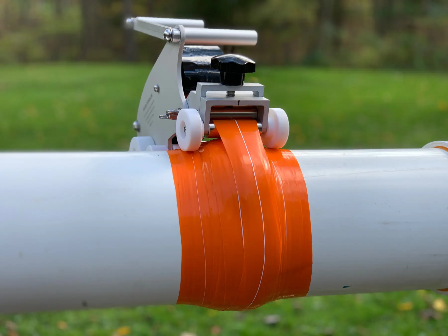
Purpose-developed construction devices
Dedicated devices support controlled formation at the Field without turning the work into a fixed-product installation. Public imagery shows the equipment and the progressive formation; it does not show the parameters that would make the work copyable.
Field-facing capability
−90 °C to 260 °C
Operating temperature range
Field-facing capability range. Each Field is assessed against its own conditions.
Up to 69 kV
Field-configured electrical insulation
Field-configured. Not a fixed product rating.
600 mm
Largest pipe diameter constructed in the Field to date
Demonstrated Field construction, not a stated maximum capability.
> 50 years
Material service-life basis
Material service-life basis.
> 10 years
Demonstrated Field operation
Demonstrated Field history to date.
Under pressure
In-service construction
Where Field conditions permit.
No hot work
ISB construction
No powered installation equipment, where Field conditions permit.
Where the Method has been applied
Functions
- Leak-control sealing
- Electrical insulation
- Corrosion protection
Media / services
- Water
- Gas
- Steam
- Organic solvents
- Petroleum and petroleum-based media
Environments
- Indoor
- Outdoor
- Buried
- Submerged
- Oil-immersed
- Radiation-exposed
Geometries
- Straight pipe
- Elbow
- Tee
- Reducer
- Valve
- Flange
- Constrained / irregular Field geometry
Demonstrated Local Compressive Performance
≈ 955 lbf
Measured force
Measured under the stated V65 Tensioner test configuration.
0.2 inch
Sensing area diameter
The measurement is local to this sensing area.
≈ 95.5%
Share of sensor full scale
Of the sensor's 1,000-lbf full-scale capacity.
≈ 30,400 psi / 209.6 MPa
Equivalent average local pressure
Calculated average over the stated sensing area, under the stated test configuration.
What this measurement is and is not
- This is a local measurement under one stated test configuration. It is not a universal pipeline operating-pressure rating.
- The test did not determine the maximum ISB compressive-clamping capability, because the measured force approached the sensor's full-scale limit.
- Layer count and other transferable construction parameters are not published.
- Local compressive performance is one input to the stopping-and-sealing relationship. Effective opening area, pipe diameter, curvature, geometry and force direction also govern it.
Not published
- Layer counts and other transferable construction parameters.
- Material combinations, winding parameters and construction sequence.
- Case-specific Solution logic developed for one unique Field.
Public content explains what is needed to understand the Method. It is not a construction tutorial. A Solution developed for one unique Field must not be copied into another Field without new DendroSeal Understanding.
Field Link
The connection layer between the Field and DendroSeal. Reality can arrive before anything else is settled.